Elevation Alignment#
Why elevation alignment matters#
In most venues, seats must be placed at varying elevations to maintain sightlines — seats on upper tiers sit higher than those at the front. The application aligns each seat's elevation to the floor geometry in the model, automating what would otherwise be tedious manual adjustment.
Hosting#
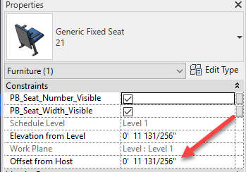
Seat families are hosted to the same level or workplane as their row reference line. If a reference line is hosted to Level 1, its seats are also hosted to Level 1. Seats are then offset vertically from that host based on the chosen alignment method.
Floor alignment#
Floor alignment determines seat elevation by finding a floor (or other approved reference element) near the host reference plane. The seat is offset upward from the top surface of that floor so it sits on top of it. This is the most useful setting for sloped or stepped seating sections.
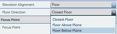
The Floor Direction setting controls where the application looks:
- Down — Looks below the reference plane for a floor
- Up — Looks above the reference plane for a floor
- Closest — Uses whichever floor is nearest in either direction
The application searches for elements in the following Revit categories:
| Category | Typical use |
|---|---|
| Floors | Concrete slabs, raked floor surfaces, tier treads |
| Generic Models | Custom riser or tier geometry modeled as Generic Model families |
| Specialty Equipment | Riser or platform elements categorized as Specialty Equipment |
Elements in both the current model and any linked Revit models are searched. Mass elements are not recognized. The maximum search distance is set by the Maximum Floor Distance in User Defaults. Which categories are searched can be configured in the Miscellaneous Settings tab.
Tip
When a reference plane is placed above the highest tier, setting Floor Direction to Down prevents the application from accidentally picking up floors from an upper level when placing lower-tier seats.
Note
If no approved reference element is found within the Maximum Floor Distance, the seat is placed at the elevation of the host reference plane with no vertical offset.
Reference plane alignment#
Reference Plane alignment places seats directly at the elevation of the host reference plane with no floor search or vertical offset. This is useful when tiers are already established with dedicated reference planes at the correct elevations.
Calculated alignment#
Planned feature
A future version of the application will provide sightline-based elevation calculation using the assigned focus point. This feature is beyond the scope of the current release.
Troubleshooting elevation results#
If seats are landing at unexpectedly high or low elevations when using Floor alignment, the most common cause is that the relevant floor or riser elements are not visible in the internal 3D view the application uses for the intersection check.
The application fires vertical rays inside a dedicated 3D view (named in Project Defaults under 3D View Name) to find intersecting surfaces. Any element hidden in that view — through workset visibility, view filters, graphics overrides, or Revit's own category visibility — will not be detected, regardless of whether it is present in the model.
Steps to diagnose and resolve:
- Open the 3D view named in Project Defaults → 3D View Name.
- Verify that Floors, Generic Models, and Specialty Equipment elements are all visible. Check worksets, view filters, and Visibility/Graphics overrides.
- If the view has been modified and its settings are unclear, delete the view. The application will regenerate it with default visibility settings on the next seat placement.
- If elements are visible but seats still land incorrectly, check the Maximum Floor Distance in User Defaults — it may need to be increased for sections with large vertical gaps between the reference plane and the nearest floor.
See the FAQ — Seat Placement for a quick-reference checklist.