Placing Reference Lines#
Using the Place Reference tool#
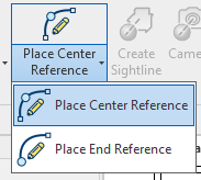
Row reference lines are placed using the Row Reference split button in the Tools panel. The dropdown offers two options:
- Place Center Reference — for center sections
- Place End Reference — for side sections aligned to an aisle edge
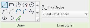
After selecting an option, the command behaves like the standard Revit model line tool. Choose a line or arc type and click to draw. The correct Performance Seating linestyle is applied automatically.
Using standard Revit model lines#
Because a row reference line is simply a model line with a specific linestyle, you may also use the standard Revit model line tool. The line must be assigned the Center or End linestyle name configured in Project Defaults. This is a common approach when offsetting from slab edges.
Geometry requirements#
- Any non-closed line or arc may be used.
- A closed circle or full ellipse will not work and will produce an error message.
- On curved references, avoid radii that are too tight for adjacent seat standards to clear each other. The application does not compensate for corners or overly tight curves.
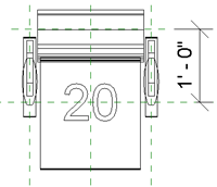
Insertion point offset#
Reference lines should be placed at the seat insertion point — the pivot location
used for rotating seats along curved rows. This typically means offsetting inward
from a step or slab edge. Each seat family has a type parameter called
PB_Plan_Datum_Offset that holds the recommended offset distance (1'-0" for the
Generic Fixed Seat).